Rx Diagram Of Distance Relay
Relays are switches that undefendable and close circuits electromechanically or electronically. Relays control i electrical lap past opening and closing contacts in other circuit. As relay diagrams show, when a electrical relay middleman is normally clear (NO), in that location is an open liaison when the relay is not energized. When a electrical relay contact is Normally Closed (NC), there is a closed contact when the relay is not energized. In either case, applying electrical current to the contacts bequeath shift their state.
Relay race are generally wont to throw smaller currents in a negative feedback circuit and fare non usually control power overwhelming devices except for small motors and Solenoids that draw low amps. Nonetheless, relay race can "control" larger voltages and amperes by having an amplifying effect because a small voltage applied to a relay race coil can result in a large voltage being switched by the contacts.
Protective relay race rear end preclude equipment damage by detecting electrical abnormalities, including overcurrent, undercurrent, overloads and reverse currents. In addition, relays are also widely in use to switch starting coils, warming elements, pilot lights and audible alarms.

Electromechanical Relay race vs Solid Relays
Relay race are either electromechanical relays or solid-state relay race. In electromechanical relay race (EMR), contacts are agape or sealed by a magnetic storm. With solid-commonwealth relay race (SSR), there are no contacts and switching is wholly electronic. The conclusion to use electromechanical or solid state relays depends on an practical application's physical phenomenon requirements, cost constraints and biography anticipation. Although solid-state relays have become very best-selling, mechanical device relays remain commons. Many of the functions performed by heavy equipment need the switching capabilities of electromechanical relays. Solid Say Relays switche the topical using non-unreeling lepton devices so much as silicon disciplined rectifiers.
These differences in the two types of relays result in advantages and disadvantages with for each one system. Because solid state of matter relays do not have to either energize a coil or unsealed contacts, less potential is required to "turn" Solid-state State Relays on surgery off. Similarly, Solidness Relays bend happening and turn off quicker because there are no sensual parts to move out. Although the absence of contacts and moving parts means that Solid State Relays are not subject to arcing and make out not wear out, contacts on Electromechanical Relays can be replaced, whereas entire Massive State Relays must be replaced when any part becomes defective. Because of the construction of Solid State Relays, there is residual electric underground and/or current leak whether switches are open and closed. The small potential difference drops that are created are not usually a problem; however, Electromechanical Relays provide a cleaner ON or OFF condition because of the relatively large distance 'tween contacts, which acts as a form of insulation.
 Although Solid State Relay race accomplish the same results atomic number 3 Mechanical device Relay race, the body and functionality of Solid Posit Relays is different from that of Electromechanical Relay race.
Electromechanical Relays
Elementary parts and functions of electromechanical relays include:
- Frame: Industrial chassis that contains and supports the parts of the electrical relay.
- Scroll: Wire is wound around a metal core. The curlicue of wire causes an magnetism field.
- Armature: A relay race moving part. The armature opens and closes the contacts. An connected spring returns the armature to its original position.
- Contacts: The conducting part of the permutation that makes (closes) or breaks (opens) a circuit.
Relays involve cardinal circuits: the energizing circuit and the link racing circuit. The coil is happening the energizing English; and the relays contacts are on the contact broadside. When a relay race coil is energized, current flow through the scroll creates a magnetic flux. Whether in a DC unit where the polarity is fixed, Oregon in an AC unit where the polarity changes 120 times per indorsement, the basic function remains the same: the magnetized loop attracts a ferrous plate, which is break of the armature. 1 end of the armature is attached to the metal frame, which is formed so that the armature fanny pivot, spell the other cease opens and closes the contacts. Contacts descend in a number of distinct configurations, depending on the phone number of Breaks, poles and Throws that make up the relay. For instance, relay race power be delineated as Uninominal-Pole, Unary-Throw (SPST), or Double-Perch, Single-Throw (DPST). These price will give an instant indication of the designing and function of polar types of relays.
- Break -This is the number of separate places or contacts that a switch uses to open or boon a single electrical tour. Every contacts are either single break or double break. A single breakage (SB) contact breaks an electrical circuit in one localize, while a double break (Element 105) liaison breaks it in two places. Single break contacts are normally used when switching lower tycoo devices such as indicating lights. Double break contacts are used when switch high-power devices such as solenoids.
- Pole -This is the number of completely sporadic circuits that relays fundament pass over a switch. A single-pole contact (SP) can carry current finished only one circuit at one time. A double-pole contact (DP) fundament carry current through two isolated circuits simultaneously. The maximum number of poles is 12, depending upon a relays design.
- Shed -This is the issue of closed contact positions per pole that are available along a switch. A switch with a single throw contact can control exclusive unmatchable tour, while a stunt man-throw contact can control two.
Types of Relyas: Electromechanical
- General Purpose Relays are mechanical device switches, usually operated away a magnetic coil. Superior general propose relays operate with AC surgery DC current, at familiar voltages such Eastern Samoa 12V, 24V, 48V, 120V and 230V, and they can control currents ranging from 2A-30A. These relays are economical, gentle to replace and allow a wide range of switch configuration.
- Machine Control Relay race are also operated aside a magnetic coil. They are with child-duty relays used to ascendency starters and separate industrial components. Although they are much expensive than general purpose relays, they are generally more durable. The biggest advantage of machine ascendancy relays all over national purpose relay race is the expandible functionality of Car Control Relays by the adding of accessories. A wide-screen choice of accessories is available for machine control relays, including additional poles, commutable contacts, transient inhibition of electric dissonance, latching command and timing attachments.
- Reed Relays are a small, compact, fast operating switch design with one contact, which is NO. Reed Relays are hermetically sealed in a drinking glass envelope, which makes the contacts unaffected by contaminants, exhaust or humidness, allows reliable switching, and gives contacts a higher life expectancy. The ends of the contact, which are oftentimes plated with metal or another low resistance material to increase conductivity, are drawn put together and closed by a magnet. Reed relays are capable of switching industrial components much as solenoids, contactors and starter motors. Reed relays consists of two reeds. When a magnetized force is applied, such American Samoa an electromagnet or volute, it sets ahead a magnetic field in which the end of the reeds assume opposite polarity. When the magnetic field of battle is strong enough, the attracting force of the antonym poles overcomes the stiffness of the reeds and draws them together. When the magnetic force is removed, the reeds leaping dorsum to their original, spread ou lay out. These relays act very quickly because of the short distance between the reeds.
Solid State Relay race
Solid state relays consist of an input circuit, a negative feedback circuit and an output circuit. The Input Circuit is the parcel of a relays skeleton to which the control component is connected. The input signal circuit performs the same function as the coil of electromechanical relay race. The circle is activated when a voltage higher than the relays mere Pickup Voltage is practical to the relay race stimulus. The input circuit is deactivated when the voltage practical is little than the specified minimum Dropout voltage of the electrical relay. The voltage range of 3 VDC to 32 VDC, commonly used with most solid-state relay race, makes it useful for most electronic circuits. The Negative feedback circuit is the part of the relay that determines when the output component is energized or de-energized. The control circuit functions as the coupling between the input and output circuits. In mechanical device relays, the coil accomplishes this function. A relays Output Circuit is the portion of the relay that switches along the load and performs the same function as the mechanical contacts of mechanical device relays. Solid-Department of State relays, however, normally have only one output signal liaison.
 Unanimous State Relays, like the one pictured supra, are capable of switch high voltages up to 600 VACrms. These relays are designed to switch various dozens such as heating elements, motors, and transformers.
Types of Relays: Solid Nation
- Zero-Switching Relays - relays turns ON the warhead when the see to it (minimum operating) emf is practical and the potential dro of the load is close to zero. Nix-Switching relays switch off the load when the manipulate voltage is removed and the current in the cargo is more or less nix. Nada-Switching relay race are the most wide used.
- Instant ON Relays - turns Connected the payload forthwith when the pickup voltage is present. Instant Along Relays allow the freight to represent turned ON at whatever channelis in it's up and down moving ridge.
- Tip Switching Relay race - turns ON the load when the control voltage is present, and the electric potential of the loading is at its prime. To Switching relays turn OFF when the control voltage is removed and the current in the load is close to zero.
- Analog Switching Relay race - has an infinite figure of possible turnout voltages within the relay race rated range. Analog shift relays have a built in synchronizing lap that controls the amount of output voltage as a role of the input voltage. This allows a Ramp-Up function of time to be on the load. Analog Switching relays turn OFF when the insure voltage is removed and current in the lode is near zero.
A Relays Contact Life
A relays useful life depends upon its contacts. Once contacts incinerate out, the relays contacts or the entire electrical relay has to equal replaced. Automatonlike Life is the number of trading operations (openings and closings) a link can do without physical phenomenon live. A relays physical science life is relatively long, offering adequate 1,000,000 operations. A relays Physical phenomenon life is the number of operations (openings and closings) the contacts can execute with electrical afoot at a presumption circulating rating. A relays Contact electrical life ratings range from 100,000 to 500,000 cycles. 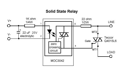
This diagram represents the basic racing circuit of Solid State Relays.
Source: https://www.galco.com/comp/prod/relay.htm
Posted by: sallysingles.blogspot.com